Dry Tank Technology Project Development News
This page shows the development of the Dry Tank Technology project demonstartor. The first three prototypes were completed in this phase. Below, you can see the completed prototype.
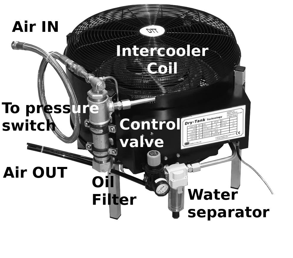
The current demonstrator consists of a HeliConeTM intercooler coil. This intercooler is a high quality, finned copper tube containing a custom turbulation element. It is capable of cooling compressed air direct from the compressor head to ambient temperature even when the input temperature is over 100oC. A large fan is mounted below the intercooler coil and blows cool air, at ground level, through the intercooler.
The DTT demonstrator is also equipped with a high temperature oil filter capable of dealing with extended operational use.
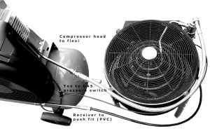
The unit is connected between the compressor head and the receiver (air in and out). A small pipe is also connected, via a tee-piece, to the compressor pressure switch input port. This ensures the DTT will switch on only when the compressor is powered.
Contents
Benchmark Testing
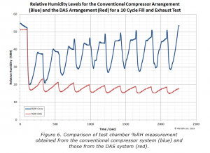
The DTT prototype has undergone a large range of lab-based performance tests and is currently being independently evaluated through a series of user trials. Some typical results can be seen in the graph below. The shows the relative humidity level of the compressed air delivered after a number of receiver fill and empty cycles. The compressed air is passed into a test chamber where its absolute humidity, temperature and pressure is measured. The blue curve shows the change in relative humidity of the compressed air obtained from a standard compression arrangement. The spikes in the response after the second cycle relates to the generation of liquid water in the test chamber. The red curve indicates the response of compressed air dried by the DTT system. It should be noted that during these cycle tests that the delivered air gets drier and drier. This is due to the fact that the unsaturated compressed air will “pick up” any liquid moisture in the compressor system, tanks and pipework, effectively drying out the system.
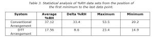
The data shown in the table below give an idea of the maximum, minimum and range of %RH levels obtained using the standard and DTT systems. Thers is a significant difference in the range of %RH readings between the two systems. The large range of the conventional arrangement is due to the %RH figure levels following the pressure in the receiver. In the case of the DTT system, where the majority of the water was removed before the compressed air is stored in the receiver, the variation in %RH is very small.
Form the table it can be seen that the converntional compressor arrangement has more than twice as much water in the system than that dried by the DTT.
Field Trials
The DTT system is currently undergoing field trial testing with a range of users. I’ll report on the results of these later.
See Also
Dry Tank Technology. A new technology to provide water-free compressed air.
Benefits of Dry Tank Technology. How this new technology will save you money and grief.